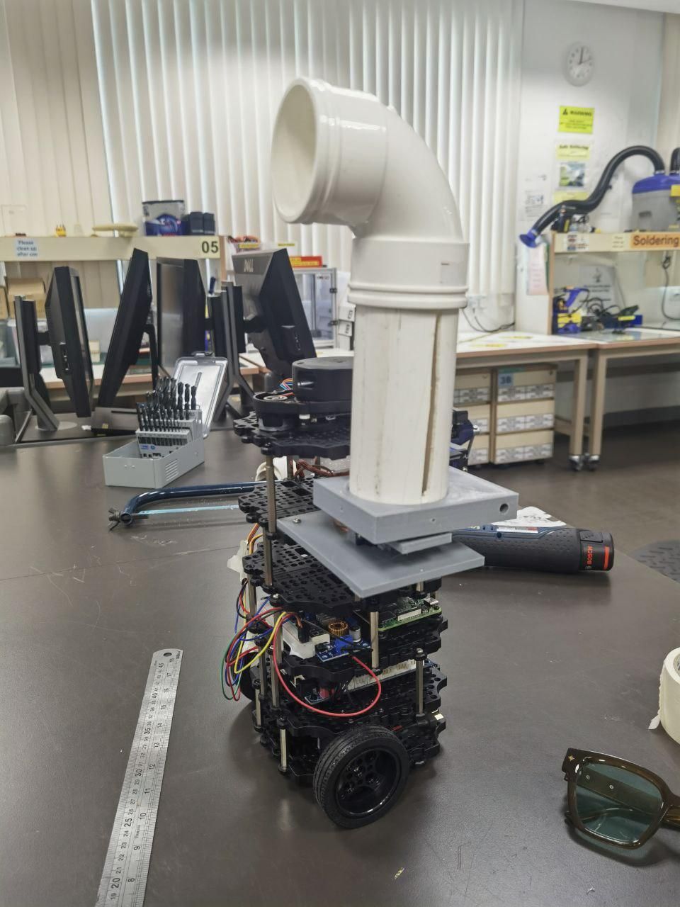
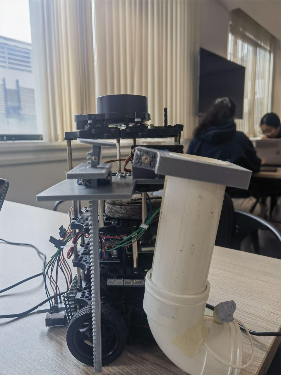
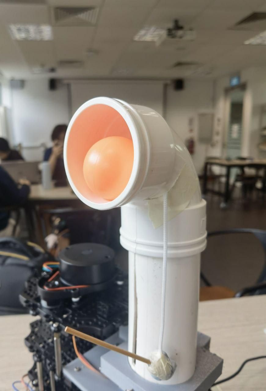
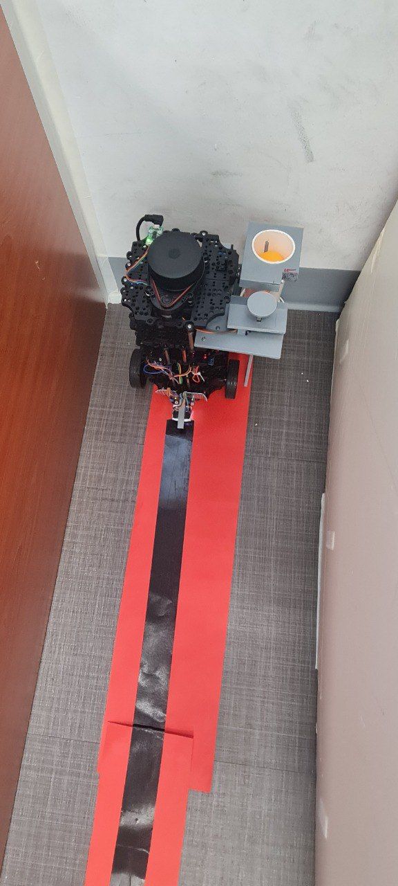
Fig 1Stowed: the cartridge hangs beside the robot, below the LiDAR plane.Fig 2Launch: rotated 180° upright, with the exit about 350 mm up, over the bucket.Fig 3Line following to the bucket.
EG2310 is NUS's systems design module: a five-person team builds a TurtleBot that navigates a maze, unlocks a door over HTTPS and delivers five balls into a bucket. The robot navigated by line following in the final run. Another mechanical engineering student and I did the mechanical side and designed the ball launcher.
Launcher design
The TurtleBot's LiDAR needs a clear 360° scan plane, so nothing can sit above the deck while the robot navigates. We designed a periscopic launcher that stows below the LiDAR plane on the side of the robot, then rotates 180° upright so the exit sits over the bucket. We chose it over a flywheel launcher because it holds all five balls, keeps the LiDAR plane clear, and delivers with more certainty.
Cartridge. A 57 mm OD / 46 mm ID PVC pipe with a 90° bend, holding all five balls. A weighted stopper pin keeps them in until the cartridge turns upright, then drops out under its own weight.
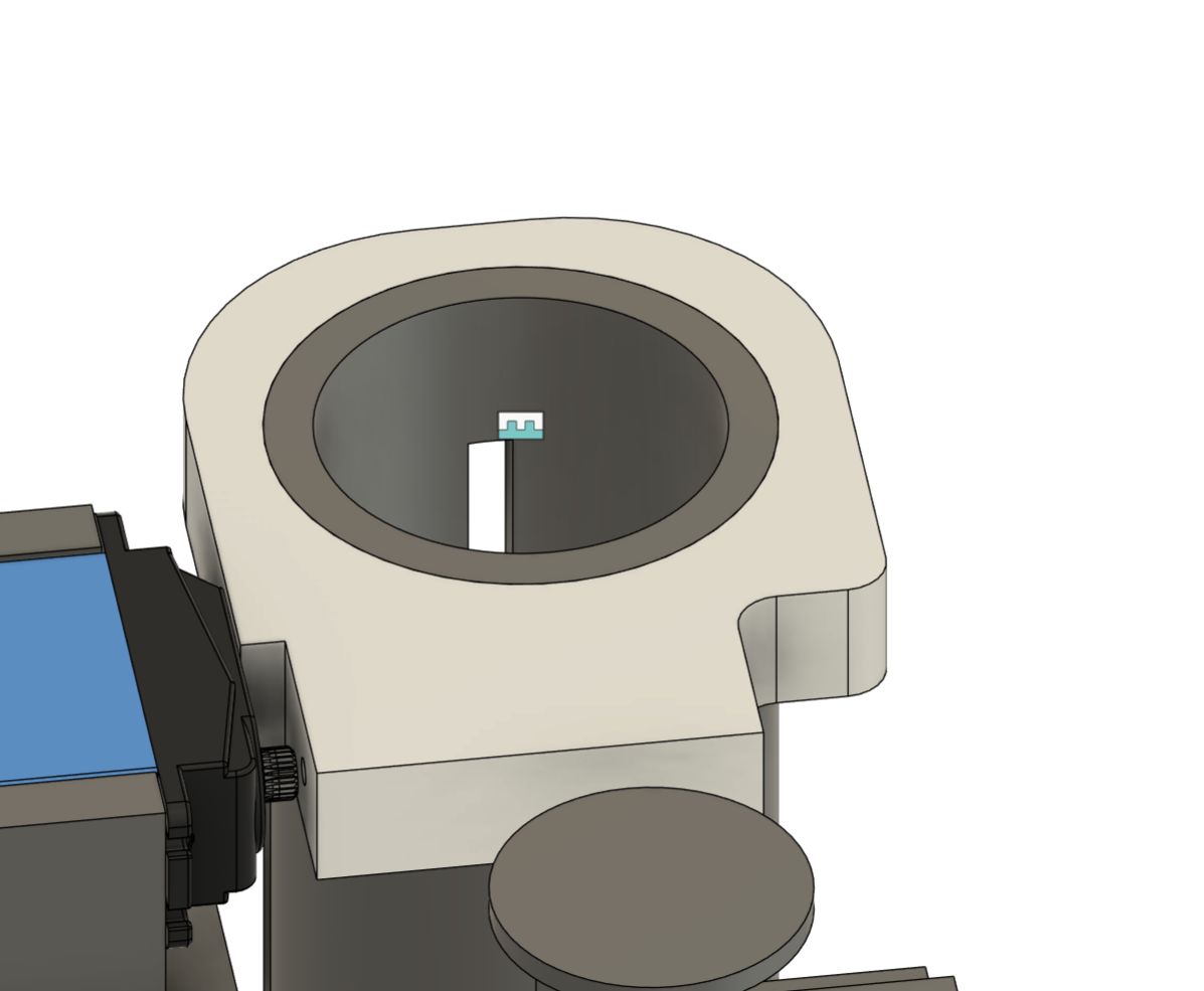
Rotation. A servo turns the cartridge holder 180° into launch position.
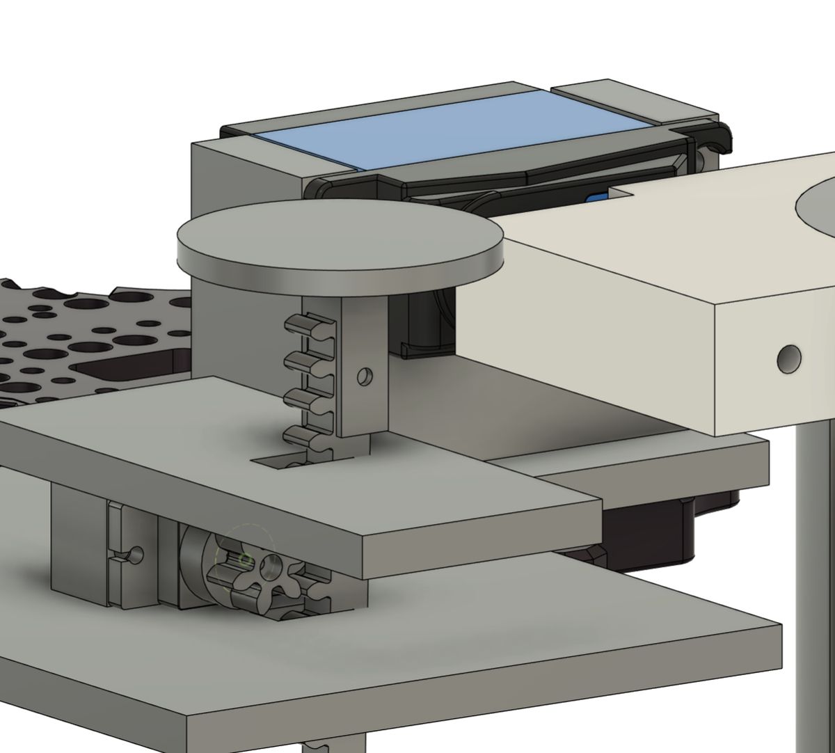
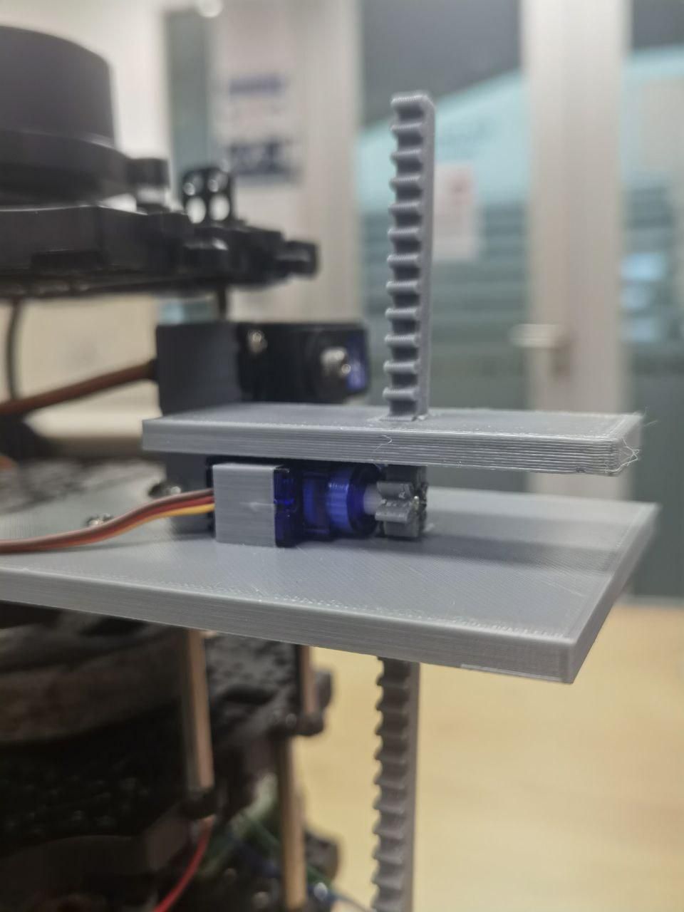
Pusher. A continuous-rotation FS90R servo drives a printed rack and pinion. When upright, the open bottom of the cartridge slots over the pusher platform, and the rack pushes the balls up and out.
Mount. A printed platform carries both servos and bolts to the TurtleBot's waffle plate.
Fig 4CAD: rack-and-pinion pusher on the mount platform.Fig 5CAD: cartridge holder on the rotation servo.
Servo sizing
The rotation servo swings the loaded cartridge through a half turn. We sized it from the cartridge's weight acting at a 0.2 m arm.
Loaded cartridge 0.2475 kg at a 0.2 m arm Load torque = 0.2475 × 9.81 × 0.2 ≈ 0.49 N·m With a 3× safety factor ≈ 1.46 N·m ≈ 15 kg·cm
The plan was an SPT5435LV positional servo, and the 3× factor was worked against it. We used an SPT5535LV with a similar torque rating that was already on hand. It is a continuous-rotation servo, so "180°" became a timed PWM command, calibrated on the robot.
The 0.2 m arm comes from the original 200 mm cartridge. Shortening it to 150 mm later (see below) cut the load torque, so the final build had more margin than the calculation shows.
What changed in testing
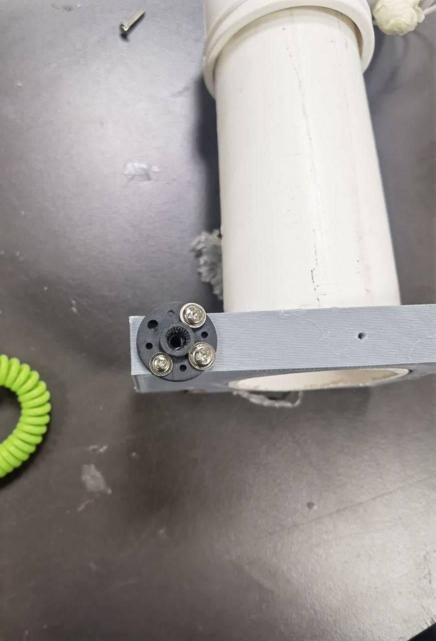
Shaft joint. The cartridge holder was first clamped to the servo shaft with an M3 bolt, relying on bolt tension and friction. It slipped, the servo had to over-rotate to compensate, and the bore wore out until it could no longer make 180°. We replaced it with the servo's own splined coupler, screwed to the holder and bolted through with a 55 mm M3 bolt. The splines give a positive 1:1 drive.
Pusher platform. The first platform tipped inside the tube instead of travelling straight up. It was redesigned as a printed part mounted on the rack.
Cartridge length. Shortened from 200 to 150 mm so it could stow vertically in the home position. It still reaches about 350 mm in launch position, enough to clear the bucket.
Stopper pin. The ball pressed the pin at an angle and stopped it dropping out, so we drilled its hole straight through. A string ties it to the cartridge, because nothing may fall onto the floor during the run.
Cartridge mounting. Glue replaced with pilot holes and self-tapping screws.
Stability. The spinning LiDAR made the tall robot oscillate. A 500 g mass on the fourth layer settled it.
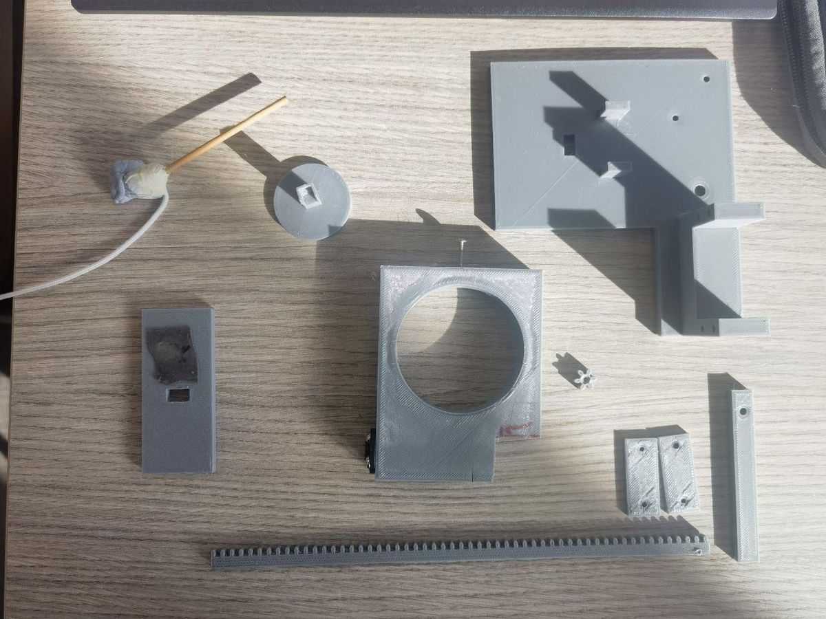
Fig 6The 3D-printed launcher parts.Fig 7Rack and pinion on the robot.Fig 8Splined servo coupler on the cartridge holder, replacing the friction joint.
All five balls went into the bucket on the final run.