Passive thermal design for a 6U CubeSat. Four simulated heatsink iterations for the 27 W Ku-band amplifier, ranked under the same vacuum load case.
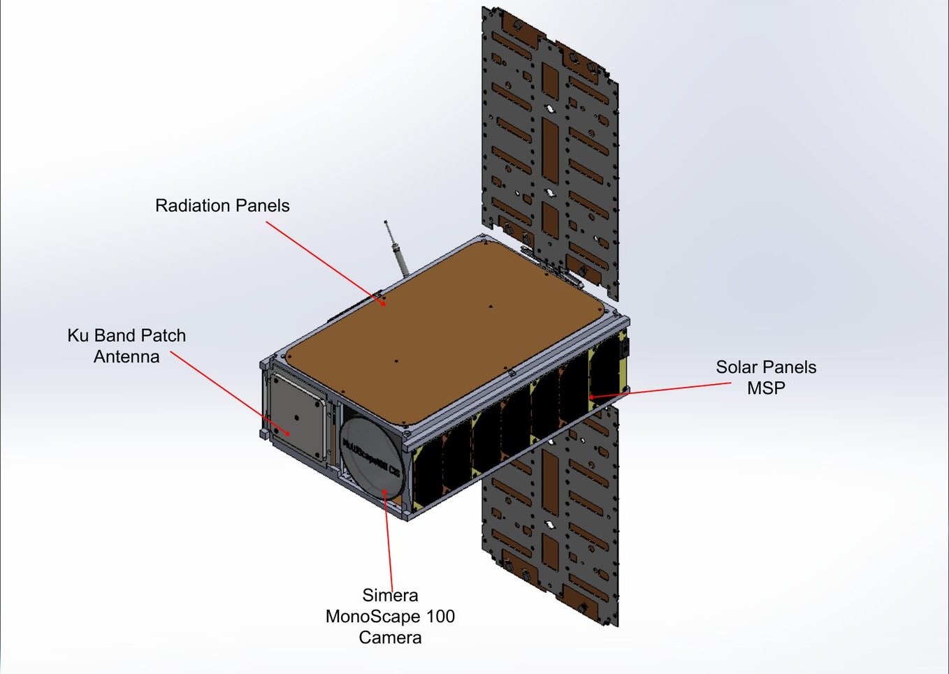
The spacecraft: 6U bus with deployable solar panels, radiator panels, Ku-band patch antenna and the MonoScape 100 camera. Team CAD.
PassedCritical design review
Planned launchQ2 2027 on a SpaceX rideshare
4 iterationsHeatsink designs ranked in simulation
OwnedThermal design, power budget
RoleDeputy team lead; thermal and mechanical co-lead
WhereNUS, with NuSpace and OSTIn
PeriodJul 2024 – Dec 2025
LaunchQ2 2027
Fig 1Simulated peak temperature of the Ku-band amplifier during a 27 W, three-minute downlink, for each heatsink iteration, all run under the same case. Read as a ranking, not flight temperatures (see the note under Heatsink iterations).
What it is
Galassia 5 is a 6U CubeSat built at NUS with NuSpace and OSTIn. Its mission is to demonstrate on-orbit AI image processing and a direct-to-VSAT Ku-band downlink, for maritime monitoring over Southeast Asia. It is planned to launch in Q2 2027 on a SpaceX rideshare. I was deputy team lead and the thermal and mechanical co-lead: I co-led the three-person mechanical team with Aakash Jayadeep and was in charge of thermal, inside a 12-person programme that passed its critical design review.
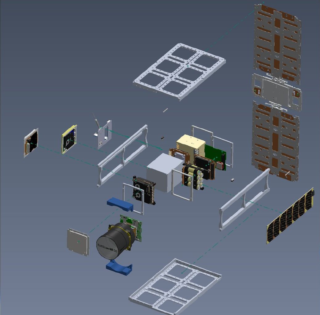
Fig 2Exploded view of the spacecraft. Team CAD.
The thermal problem
The spacecraft packs a single-board computer, an AI accelerator, the camera, a Ku-band upconverter (the amplifier) and a battery into 6U. Without thermal control these parts can exceed their operating limits or see steep thermal gradients, which can cause structural or optical misalignment. Galassia 5 needs a stable thermal environment for continuous AI processing and a reliable Ku-band downlink.
In low Earth orbit there is no convection. Heat leaves only by conduction into the structure and radiation to space. Each orbit brings direct solar flux (~1361 W/m²), Earth albedo (~410 W/m²) and Earth infrared (~230 W/m²), and the spacecraft cycles between sunlight and eclipse. A CubeSat has very little thermal mass, so heat builds up quickly, and dense packing leaves little room for it to escape. The result is fast temperature swings every orbit and steep gradients.
The Ku-band amplifier is the worst case. It dissipates up to 27 W during a three-minute transmission and, in the baseline design, had no thermal path of its own. Its manufacturer limit is 55 °C.
Requirements
Component limitsEvery part inside its datasheet range in worst-case hot and cold orbits
System targetsSunlit about 0 to 50 °C; eclipse about −10 to 50 °C
PowerPassive preferred: heaters and louvres cost power the payload needs
IntegrationFits the existing layout; vacuum-safe, no outgassing
Design constraints and groundwork
ConstraintWhy it limits the design
Limited volume, dense packingElectronics are tightly stacked and share structural interfaces
Limited radiator areaExternal faces are taken by solar panels and antennas
High internal power densityContinuous dissipation from the computer, AI accelerator and RF amplifier
Restricted power budgetPower goes to payload and comms first; heaters and louvres are expensive to run
Interface dependencyPerformance depends on pad thickness, surface flatness and bolt preload
Modelling uncertaintyEmissivity and contact conductance are uncertain
Before the simulations, the groundwork covered a literature review, the mass and volume budget, preliminary simulations, a thermal profile of every component against its datasheet limits, and a survey of COTS passive options: coatings and tapes, multi-layer insulation, thermal straps, sunshields, louvres, deployable radiators, phase-change materials and thermal switches.
Method
Three models, each feeding the next: MATLAB for the orbital heat environment, GMAT for the orbit and duty cycle, and SolidWorks for the transient thermal model that the heatsink was designed in.
1. Orbital environment (MATLAB)
I modelled the trajectory and sun vector over 24 hours (15 orbits) at 550 km, 98° sun-synchronous, and computed solar, albedo and Earth infrared flux on every face in sun-tracking attitude, with Earth as a ~255 K blackbody. The radiating faces (X+, X−, Y+, Z+, Z−) were black-coated 6061 with emissivity applied. The Y− face and the two deployable panels, hinged on the X−/Z− and X−/Z+ edges, used solar-cell properties (cell efficiency and packing factor), since they are covered in cells and cannot radiate efficiently.
Solar input is highest on the sun-tracking panels, then the Y+, Y− and X+ faces; X− receives the least.
Infrared and albedo heating peak on the X+ (nadir) face.
In autonomous mode the attitude drifts, so infrared and albedo move between faces. I carried an averaged face flux into the SolidWorks model.
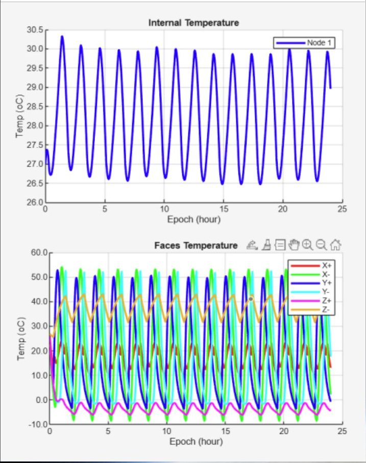
Internal temperature cycled between 26.5 and 30.5 °C. External faces swung widely.
Fig 3MATLAB model over 24 hours: internal node temperature (top) and each face (bottom).
2. Duty cycle and power (GMAT)
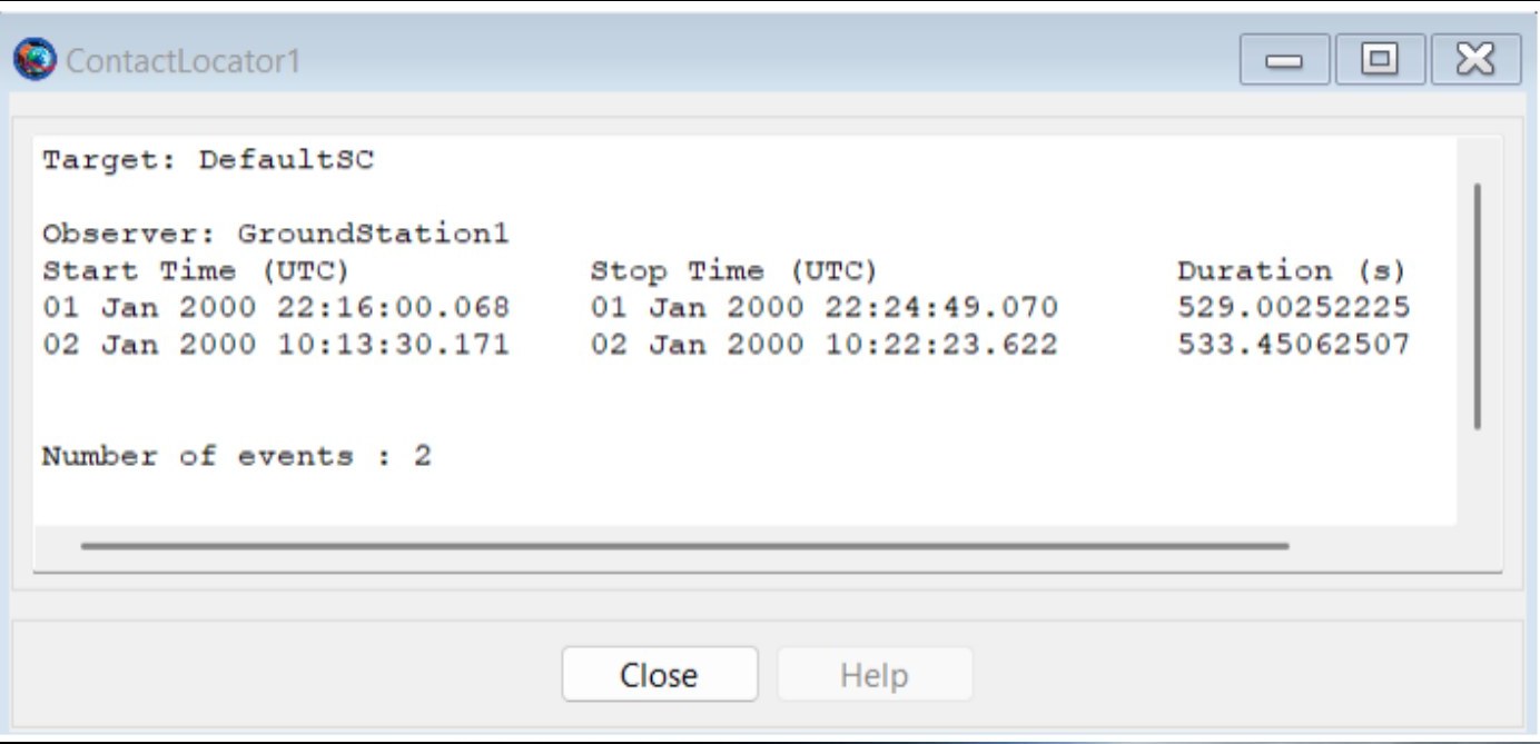
I simulated the orbit and contact windows in GMAT, with the NUS campus as the ground station. It gave two contacts a day of about nine minutes each, so the remaining 1,400+ minutes a day are autonomous. That set four operating modes per orbit, and which components are powered in each.
Fig 4GMAT contact locator: two ground-station contacts a day, each about nine minutes.
ModeDurationWhat runs
Sunlit imaging7 minCapture, onboard AI processing, Ku-band downlink
Sunlit autonomous55 minSun tracking, battery charging, critical systems
Eclipse tasking7 minNight-pass communications and delayed downlink
Eclipse autonomous27 minMinimal systems; heaters and battery for survival
I ran the full power budget through every mode and co-developed the concept of operations. The same duty cycle then set the thermal load cases, so the power and thermal models used the same timeline.
3. Transient thermal (SolidWorks Simulation)
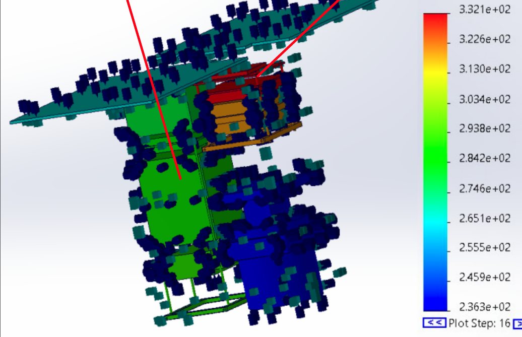
The spacecraft-level transient run found two hotspots. The single-board computer runs continuously (flight software and AI preprocessing) and peaked at 332 K (about 59 °C) in high-load imaging mode. That is inside its limit on the manufacturer's heatsink, but with no margin left. The Ku-band upconverter read 300 K (27 °C), but it had been modelled as a large placeholder block with far more radiating and conduction area than the real part, so the real part would run much hotter.
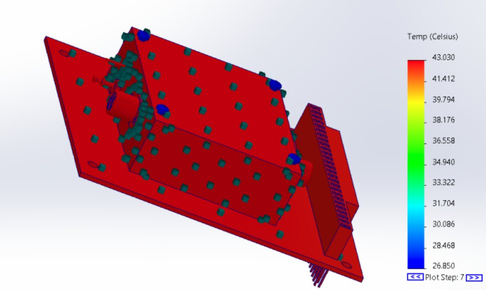
I built a component-level model of the real amplifier, mounted on a dummy PC-104 board to match its actual mounting and keep the conduction and boundary conditions consistent. It peaked at about 44 °C during a transmission: inside 55 °C, with little margin for a part that cannot be serviced.
Fig 5Spacecraft-level transient result (kelvin).Fig 6Component-level model of the amplifier with no heatsink.
Concept selection
I compared options for each function in a morphological chart and chose a fully passive conduction and radiation path.
All options considered for each function
FunctionChosenOther options considered
Heat transportAluminium baseplate and spreaderLiquid metal loop, heat pipes, graphene sheets, vapour chambers, flexible thermal strap
Thermal interfaceSilicone TIM padGraphene TIM, phase-change TIM, indium foil, pyrolytic graphite sheet, gallium liquid metal
IntegrationDirect top-mount on the amplifierModular panel, structure-embedded, stand-offs, direct chip contact, surface coating
The heat path has three steps. The amplifier dissipates up to 27 W during transmission. That heat conducts through the silicone pad, which fills microscopic air gaps and cuts contact resistance, into the aluminium heatsink. The heatsink spreads it across a larger mass and rejects it by conduction into the frame and radiation to deep space. No pipes, loops, power or moving parts are involved.
6061-T6 heatsink. High conductivity (~167 W/m·K) for fast spreading, light enough for the mass budget, easy to machine, and the same alloy as the frame for conduction continuity.
Silicone pad. 4–6 W/m·K, conforms to surface imperfections and removes trapped air, tolerates vibration, and is vacuum-compatible and clean, unlike grease.
Heatsink iterations
I started from catalogue heatsinks, the parallel-fin and cross-fin (pin-grid) shapes used in CPU coolers, phones and power electronics. Every iteration ran the same case: 27 W for 180 s, starting at 283 K, a silicone thermal pad of about 5 W/m·K, and radiation to space from the outward faces. The goal was to rank the geometries against each other under vacuum, with everything else held the same.
IterationPeak / coldest point at the peakWhy it moved
No heatsink44 °C / 26 °CBaseline
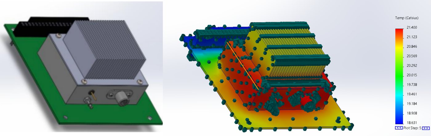
Parallel fins21.4 °C / 18 °CMore mass and conduction path, but fins mostly radiate into each other
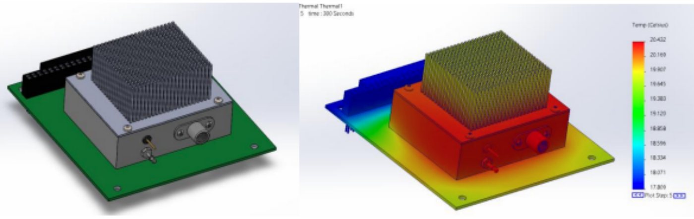
Cross fins20.4 °C / 17.8 °CMore area, almost no gain: the same view-factor problem
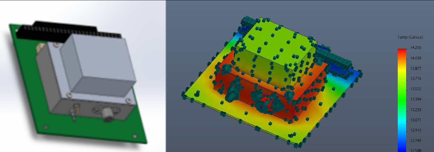
Solid block14.2 °C / 12.6 °CMost of its surface sees deep space; no fin-to-fin re-absorption
Solid block, black anodised~7.1 °C / ~5 °CEmissivity from ~0.30 (bare) to ~0.85–0.90
Fig 7Parallel fins: 21.4 °C peak.Fig 8Cross fins: 20.4 °C, almost no gain over parallel fins.
The cross-fin result was unexpected: more surface area, almost the same temperature. In vacuum, radiated power follows P = εσAT⁴, and only surfaces that see deep space count. Closely spaced fins mostly radiate into each other and re-absorb that heat, and only outward-facing, high-emissivity surfaces reject it.
P = ε σ A T⁴, with σ = 5.67 × 10⁻⁸ W/m²K⁴ Only the part of A with a clear view of deep space contributes; fin-to-fin exchange stays inside the heatsink
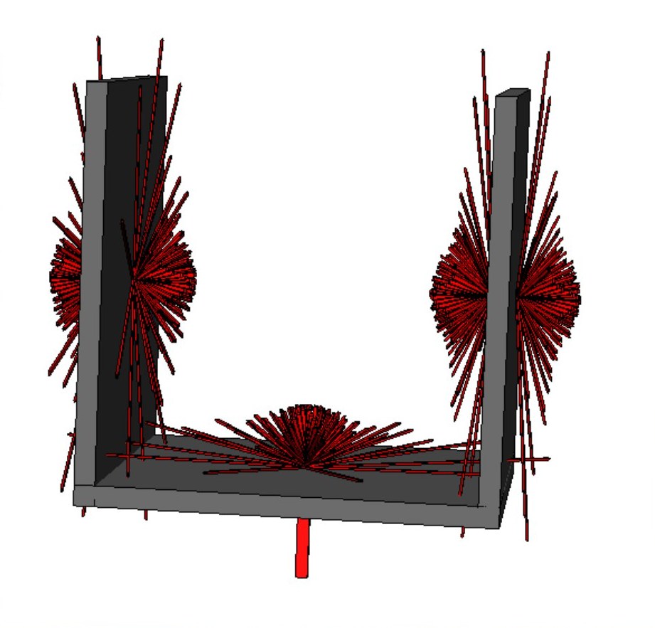
Fig 9Radiation from a fin pair: much of what each face emits lands on the neighbouring fin or the base instead of reaching space.
Closely spaced fins work well in air, but in vacuum they mostly radiate into each other and see little of deep space, so they add little cooling. A solid, high-emissivity block outperformed them.
So I replaced the fins with a solid block: a high view factor to space, no fin-to-fin re-absorption, and a continuous conduction path that spreads heat evenly through the mass. Then I raised emissivity. The bare aluminium was modelled at an emissivity of about 0.30; black anodising takes it to about 0.85–0.90, and it is vacuum-safe, light and durable with no outgassing risk.
Fig 10Solid block: 14.2 °C.Fig 11Solid block, black anodised: ~7.1 °C. Final design.
Black anodise also absorbs sunlight well (solar absorptivity about 0.9), so it suits a face that looks at deep space. On a face that sees the Sun or Earth albedo, white paint or an optical solar reflector, with low absorptivity and high emissivity, would be the better coating.
The final design is a solid 6061-T6 block, black anodised, on a silicone thermal pad, mounted directly on the amplifier. It ranked best of the four, keeps the amplifier inside its 55 °C limit with more margin than the bare part, and is fully passive with no power draw.
Read the temperatures as a ranking, not a flight prediction. The anodised block finishes below its 10 °C starting temperature while the amplifier is dissipating 27 W, so the component model sheds heat faster than the spacecraft would. All four designs ran the same case, so the comparison is like-for-like within this model. Absolute values need the full spacecraft model and thermal vacuum testing.
Next steps
Thermal straps. A pyrolytic graphite strap, flight-proven on the ASTERIA CubeSat and the Mars 2020 rover, to carry heat from the amplifier to a chassis radiator during long downlinks.
Deployable radiators. Panels that unfold in orbit to add high-emissivity area, supporting higher duty cycles without changing the internal layout.
Thermal vacuum testing. TVAC testing to confirm the model in the orbital environment, alongside random vibration testing for launch.
Specification
Spacecraft6U CubeSat; on-orbit AI imaging, Ku-band direct-to-VSAT downlink
Orbit550 km, 98° sun-synchronous
LaunchQ2 2027, SpaceX rideshare
Critical loadKu-band amplifier, 27 W for ~3 min per downlink; 55 °C limit