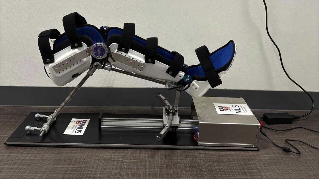
STRIDE is a lower-limb rehabilitation device for stroke patients. It drives the knee through flexion and extension and guides the hip through abduction and adduction, in one unit small enough for a Singapore HDB flat. Commercial CPM machines usually move one joint and cost SGD 1,000–5,000. Robotic exoskeletons cost over USD 50,000 and need a clinician. Our target was under SGD 1,000, and STRIDE cost SGD 807 in materials.
Video 1STRIDE running each exercise beside the manual physiotherapy it replicates: knee extension, knee flexion, then hip abduction and adduction along the rail. Physiotherapy footage: SingHealth, “Rehabilitation for stroke patients” (YouTube).
I was team lead and mechanical lead of an undergraduate research team, with Clemvision as the industry partner. Clemvision set the problem and endorsed the result. I designed the knee linkage, selected and sized the hip rail, set the geometry from anthropometric data, ran the user trials, and coordinated integration across the mechanical, electronics, enclosure and software work, including the team's cloud-connected caregiver monitoring.
Requirements
Design targets
Knee range0–110° flexion and extension, motorised
Hip range30° abduction, 10–15° adduction
User size5th–95th percentile Singaporean adult leg; 80 kg design user
CostUnder SGD 1,000 in materials
Size and massFits a bedroom or living room; around 15 kg
UseSafe without a clinician present (design target; not clinically tested)
Design
Knee drive
A NEMA 17 stepper drives a 400 mm-stroke ball-screw slide. A two-link reverse-V linkage turns the carriage's linear travel into knee rotation. One link set is hinged near the hip end, the other rides on the carriage, and they meet at a hinge at the anatomical knee. We tuned the rod lengths in CAD, then shortened them during trials until the hinge lined up with users' knees and the full 0–110° was reachable without binding. When powered, the stepper holds the ball screw in place, so the leg stays put if motion stops.
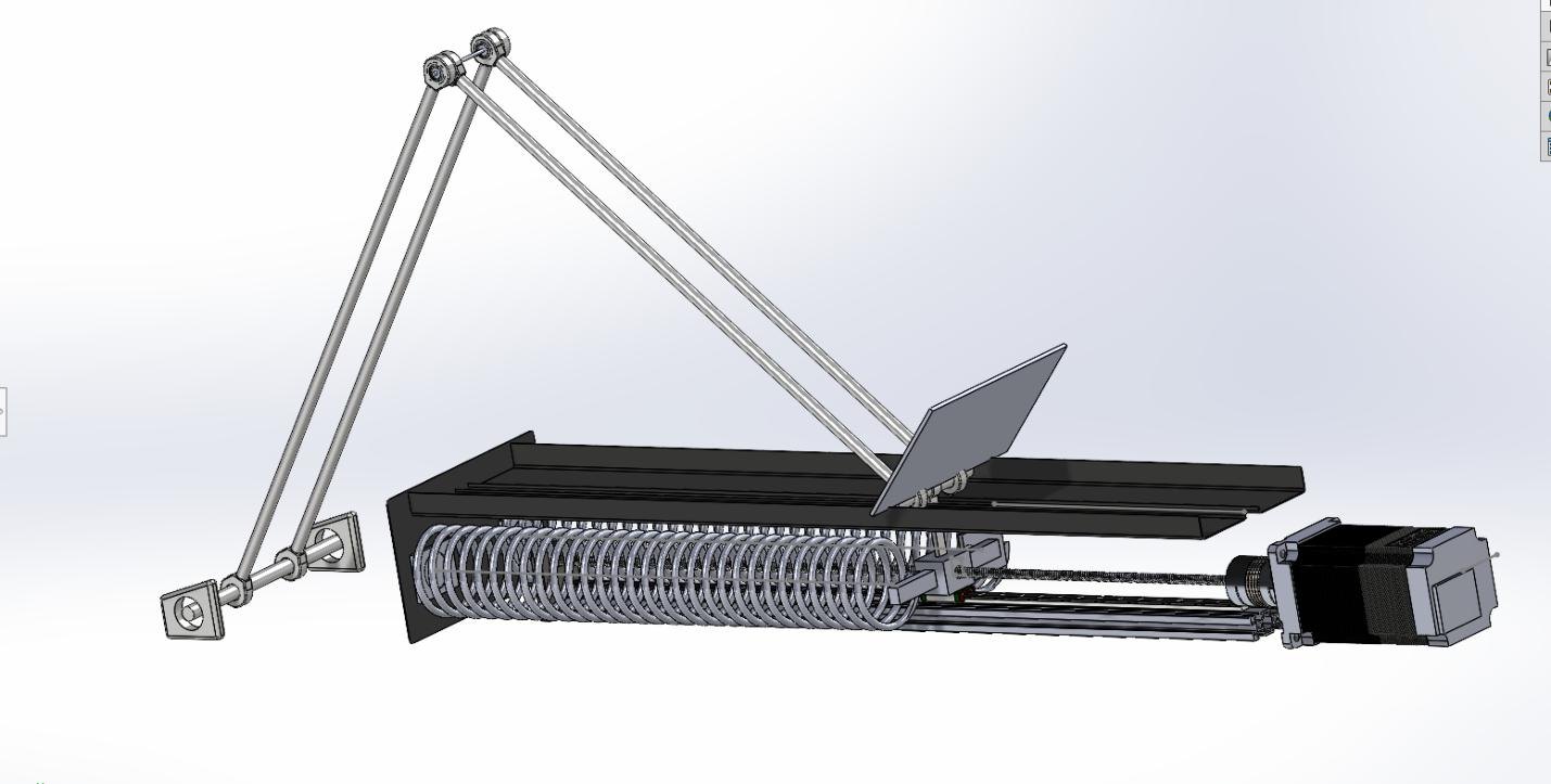
Fig 1An earlier design in CAD, which added spring assist to the drive. We dropped the springs (see Concepts rejected).
Hip module
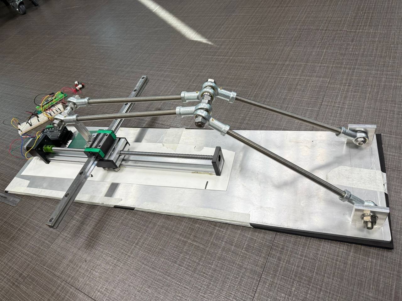
The first hip version ran on a straight rail. Users reported knee discomfort and the range was restricted, because the leg swings about the hip in an arc and a straight rail works against it. Version two uses a THK HCR15A curved LM guide with a 400 mm radius, chosen to balance the anatomical arc, the 1.275 m base length and the budget. It gave the full 30° of abduction, and volunteers reported it comfortable through the whole range. 3D-printed end-stops limit travel at both ends.
Fig 2The first version on the bench: straight hip rail across the base, ball-screw knee drive and the reverse-V linkage.
The hip is passive. The patient moves the leg, and the rail guides it and limits the arc. A motor driving abduction would put off-axis torque across the hip in the direction where stroke patients often have spasticity, so that axis has no motor.
Concepts rejected
Spring assist (the earlier design in Fig 1). Torque depended strongly on deflection, progression would need several custom springs, and suitable springs were hard to source locally.
Pneumatic or full exoskeleton. Over budget, larger, and a heavier safety burden for a first home-use prototype.
Knee only. The industry partner and the literature both pointed to hip abduction for gait stability, which is why the hip module exists.
Sizing checks
A leg is about 17–18% of body mass, roughly 14 kg for the 80 kg design user. The off-the-shelf components are rated well above that.
ComponentRatingAgainst
Ball-screw slide18 kg vertical, 60 kg horizontal~14 kg leg; the carriage carries only part of it
HCR15A curved guide≈8.33 kN dynamicDistal leg segment only
StructureSized to ~2× predicted loadExtra 10 kg pressed onto the leg in trials: no visible deflection or permanent set
Drive torque check:
Knee torque to move the shank and foot ≈ 12 N·m Force at the carriage through the linkage ≈ 150 N Screw torque = F·L / (2π·η) = 150 × 0.005 / (2π × 0.9) ≈ 0.13 N·m Typical NEMA 17 torque at working speed ≈ 0.3 N·m, a margin of about 2×
Assumptions: 5 mm screw lead and 90% efficiency, typical rather than measured motor torque. The next version moves to a closed-loop NEMA 23.
Testing and what changed
Ten healthy volunteers, 160–178 cm and 50–82 kg, tested the device over several rounds, and after each round we changed the hardware.
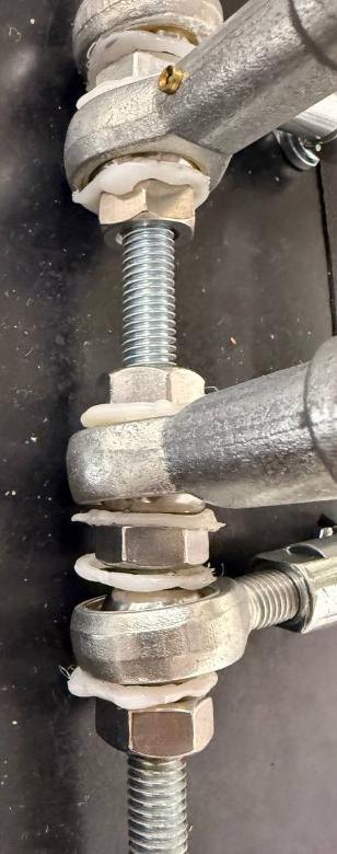
Knee twisting. During hip trials the linkage sometimes rotated about the knee's long axis instead of the hip's, because the rod-end bearings at the knee could roll axially. The knee tolerates only about 5–10° of axial rotation before it loads the ligaments and menisci. We added custom printed O-rings on the rod ends to block axial roll while leaving flexion free.
Sliding block connector. The first connector used two of the four holes on the rail block, so the block tilted and dragged. We made a new connector that uses all four, and it runs smoothly.
Loosening fasteners. Vibration backed off rod ends and bolts. We fitted spring washers and lock nuts on every linkage joint, which fixed it.
Patient interface. Bare metal, then foam that shifted, then a Velcro-strapped leg cast that spread the load across the size range, which volunteers reported as comfortable.
Noise. The first runs were loud. I tuned the TB6600 driver against its datasheet, sweeping microstepping and current to settle on half-step at 2.0 A, and added foam and leather damping layers.
Fig 3Custom O-rings on the knee rod ends, added to stop axial roll.
Requirements and how they were checked
TargetHow it was checkedResult
Knee 0–110°Software limits; range checked by eye during trialsObserved. Full range reached without binding
Hip 30° abductionCurved rail and end-stops, volunteer trialsTested. Full 30° reached; volunteers reported it comfortable
5th–95th percentile usersTen healthy volunteers, 160–178 cm and 50–82 kgPartly tested. All ten volunteers fitted after linkage and interface changes; the full percentile range is not covered
80 kg design userComponent ratings against a ~14 kg leg; extra 10 kg pressed onto the leg in trialsCalculated: structure sized to ~2× and motor torque ~2×. Tested: extra 10 kg pressed on, no visible deflection or permanent set
Under SGD 1,000Bill of materialsMet. SGD 807
Safe without a clinicianLayered safety: end-stops, homing, e-stop, current limitDesign target. Not clinically tested
Safety
Mechanical end-stops on the hip rail; software limits of 0–110° on the knee.
Limit-switch homing at start-up, so position is measured rather than assumed.
Hardwired emergency stop that cuts motor power.
Driver current limit on the open-loop stepper, and barrel dampers at the knee connection.
Trapezoidal warm-up speed profile on the knee drive, so there are no step changes in velocity.
Rounded edges and padding wherever the leg meets metal.
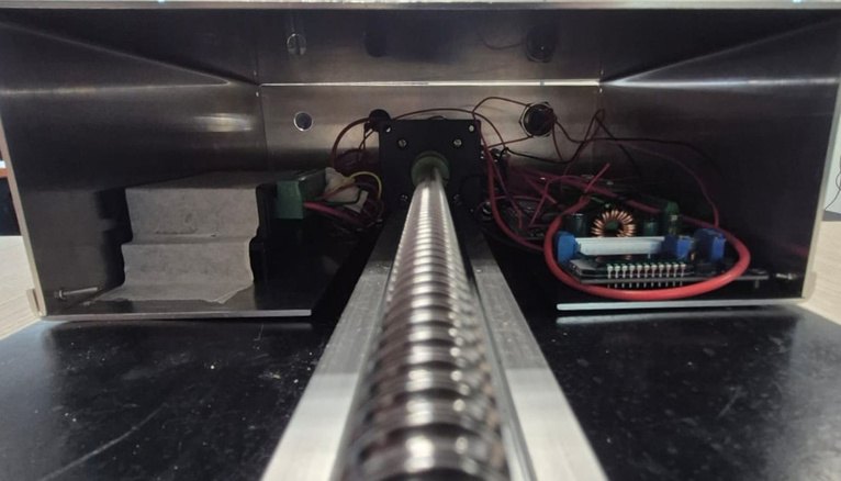
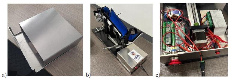
Fig 4Inside the enclosure: TB6600 driver, NEMA 17 and Teensy 4.1 on the ball-screw axis.Fig 5Enclosure: sheet aluminium base and sliding cover, shown closed and with the electronics installed.
Next revision, specified
Knee brake. A brake on the knee drive, so the leg holds position when the e-stop cuts motor power.
E-stop for the patient. The stop button moves from the enclosure side wall to within the patient's reach.
Measured range of motion. An encoder on the knee axis to log range and repeatability on every session.
Closed-loop drive. A closed-loop NEMA 23 in place of the open-loop NEMA 17.
Rod-end rings. Rubber or TPU in place of the printed rings, to stop the last of the axial roll.
Specification
Materials costSGD 807 (target: under SGD 1,000)
Dimensions1.275 × 0.22 × 0.50 m, ~15 kg
Knee drive400 mm ball-screw slide, 12 mm screw, NEMA 17, reverse-V linkage
Hip guideTHK HCR15A curved LM guide, 400 mm radius, printed end-stops